Saginaw Steering Box Rebuild - Assembly - 10/16/2016
Paint dried, parts sealed and cleaned, time to put it together.
![]()
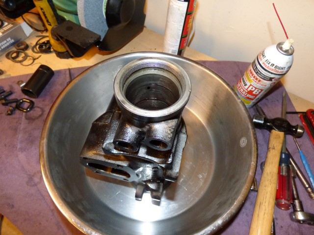
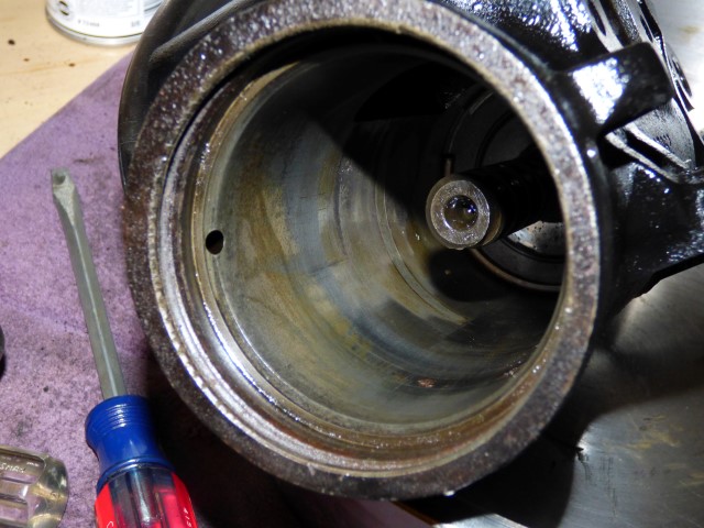
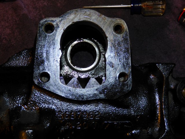
Start with an empty housing.
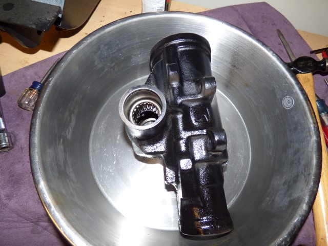
Press the bearing assembly into the housing first.
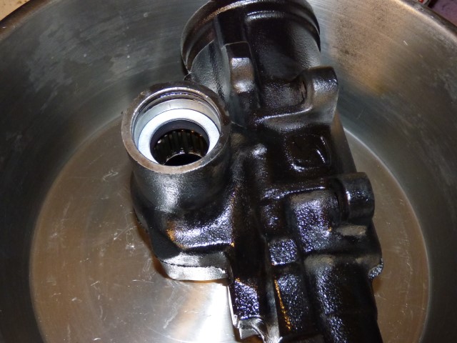
The first seal goes in followed by a washer.
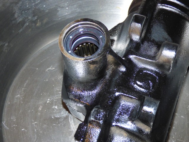
The second seal goes in. Lubed up for ease of installation. It wasn't easy, I'm not sure how you'd do this in the car with the output shaft still in place.
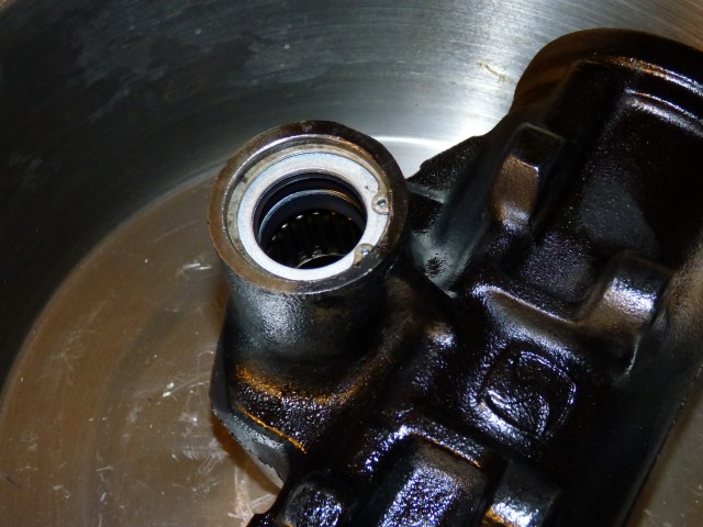
Last washer and c-clip. Note that it's the original c-clip. When I was compressing the new one in it came off and shot across the garage, never to be seen again...
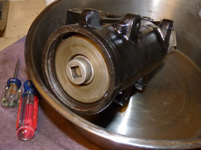
Input chamber is cleaned and wiped down with ATF.
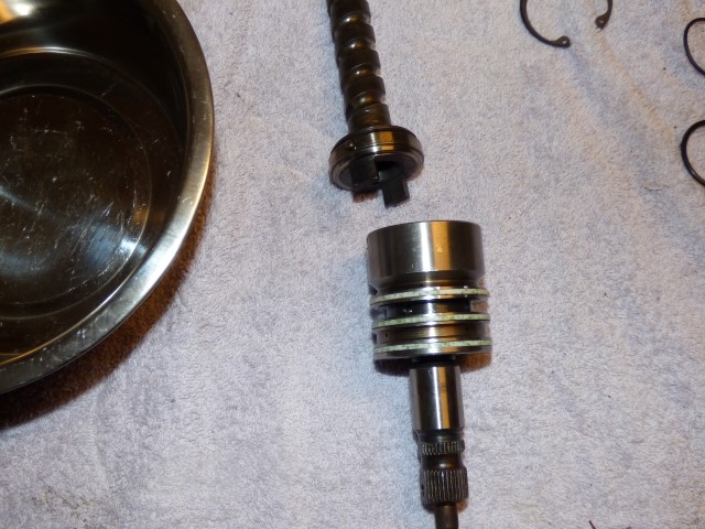
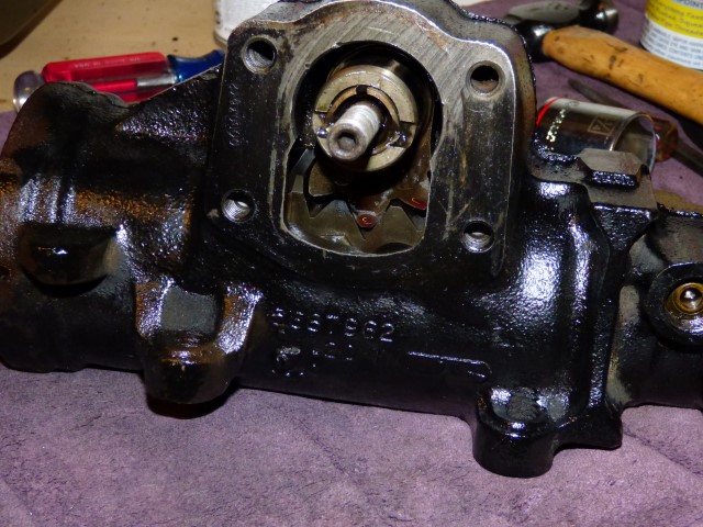
Input shaft is combined as an assembly, lubed up the o-rings, and fed in.
Input shaft goes in. It's actually easier to assemble all of the parts, turn the housing upside down, and then slide it up to avoid gravity trying to "help" separate the 2 halves from each other. Needle bearings and washers get liberally coated in ATF.

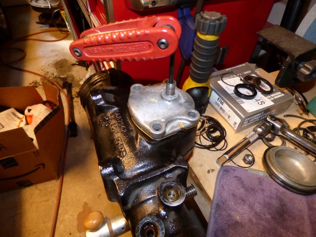
The input cover plate is lubed on the seals and bearings, then a spanner wrench is used to set the pre-load on the bearings. In this case I set it for 4.5 threads visible at this point. It "feels" correct, it's supposed to only require 11 in-lbs to turn and the tool I have for measuring it looks close enough... This is one of those tasks that isn't easy if you've never done it but knowing what it used to be combined with knowing how it's supposed to feel gets it pretty close without too much trouble.
Lock ring is tightened down to prevent the plate from working it's way loose. Important to watch and make sure the plate doesn't turn at the same time.
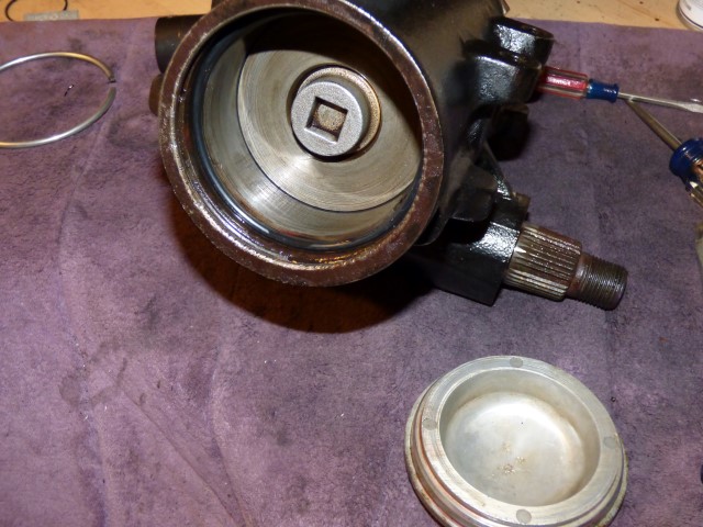
Input piston chamber is lubed with ATF to accept the piston.
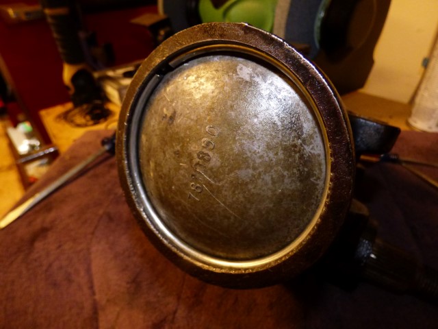
Piston drops down in. The teflon ring in the kit is a little oversize and this it is incredibly frustrating to fight getting the piston down into the housing...

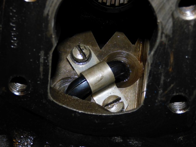
Slide the piston down to the sector plate hole and orient it to see the 2 holes as so.
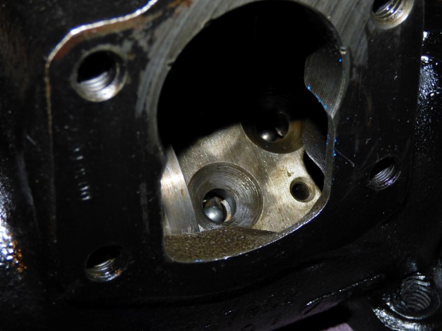
Ball bearings are installed. Start with a light one, then a dark one, in the upper right hole. You'll have to scootch the piston and input shaft a bit to move the worm gear around and get the ball bearings to go into the hole and into the chamber. A little punch without sharp edges can provide encouragement along the way. 18 balls will go in to get to this point (alternating light and dark).
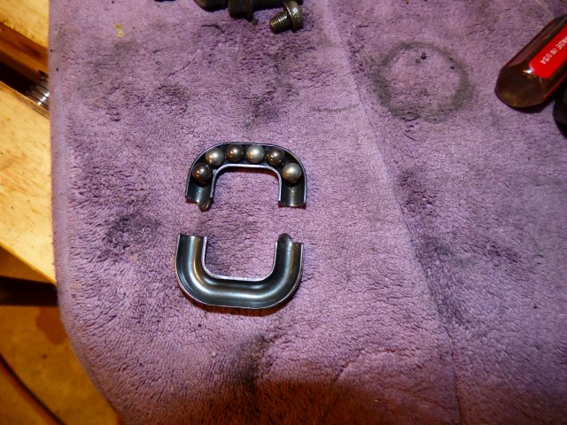
The last 6 alternating bearings go in this little guide. I use a slight bit of moly to hold each end in place to keep the bearings from falling out. This is probably the hardest part of the job between getting these last 6 ball bearings in and getting the piston assembly in.
Guide is tightened down. The ball bearings roll around on the worm gear to make the piston move up and down in the shaft as it slides on it's own without them.
Align the teeth of the piston to be vertical with the output sector shaft. The input shaft should have the flat spot UP towards to the hose fittings and the teeth will get into this position: the box is centered in this position.
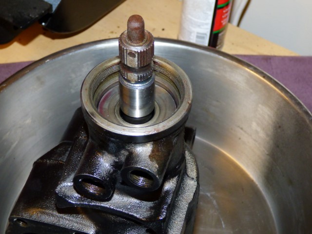
Sector shaft goes in.
Top plate gets tightened down.
The o-ring for the plug gets put into place and lubed up.
Plug is installed and metal ring pushed into the groove to keep it installed.
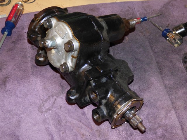
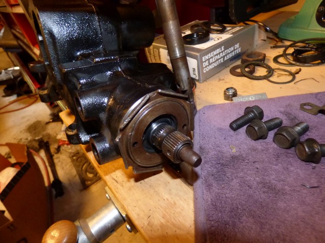
And final lash is made on the adjuster nut and box is done. You'll know this lash isn't set right by how the return to center characteristics are, plus the slop in the steering. The steering wheel will need to be corrected in both directions as you go down the road if it's too loose. If it's too tight, the box will bind and not return to center properly (BAD on the car). A little goes a long way here.
Total time to assemble if no issues: 80 minutes. There were some complications that required more adjustments to make it almost 2.5 hours, but in the end it seems to work really well. It's a full 3 turns stop to stop, no binding or looseness at all. Next test is on a running car, but the bench tests show that it shouldn't have any mechnical binding in its current state.
Return to Tech Pages
Last updated October 16th, 2016